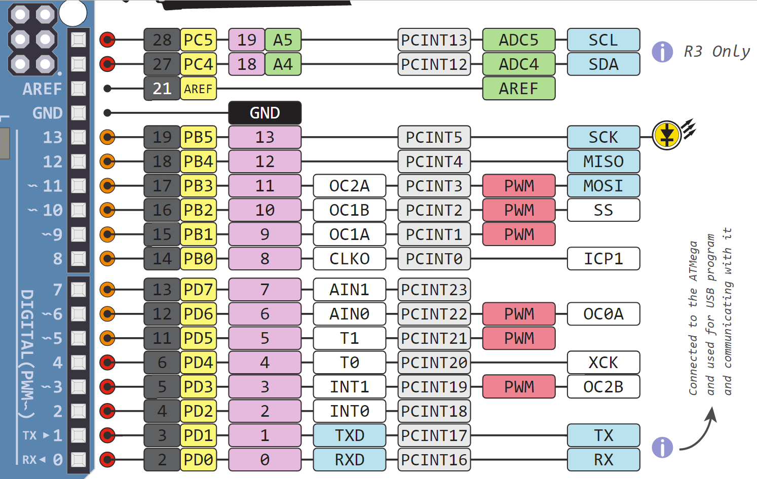
You can use the VIN pin to power the whole microcontroller with a. All power pins have a maximum current of 50 mA. The Uno has in total three power pins of which one has a supply voltage of 3.3V and two pins provide 5V. The Arduino Uno has a lot of different pins and therefore we want to go over the different kinds of pins.


GPIO1: pin is high at BOOT, boot failure if pulled LOWThere are certain pins that output a 3.3V signal when the ESP8266 boots. GPIO2: pin is high on BOOT, boot failure if pulled LOW The following list shows the state of the following pins on BOOT:
Arduino Uno Pinout Reference How To Use Analog
ESP8266 ADC – Read Analog Values with Arduino IDE, MicroPython and LuaMost of the ESP8266 development boards have a built-in LED. If you’re using a development board like the ESP8266 12-E NodeMCU kit, the voltage input range is 0 to 3.3V because these boards contain an internal voltage divider.You can learn how to use analog reading with the ESP8266 with the following guide: That GPIO is called ADC0 and it is usually marked on the silkscreen as A0.The maximum input voltage of the ADC0 pin is 0 to 1V if you’re using the ESP8266 bare chip. Analog InputThe ESP8266 only supports analog reading in one GPIO. You can read this article that investigates the state and behavior of each GPIO on boot.GPIO4 and GPIO5 are the most safe to use GPIOs if you want to operate relays. The following GPIOs output a HIGH signal on boot:Additionally, the other GPIOs, except GPIO5 and GPIO4, can output a low-voltage signal at boot, which can be problematic if these are connected to transistors or relays.
Arduino Uno Pinout Reference Software PWM In
Usually, the following GPIOs are used as I2C pins:ESP8266 allows software PWM in all I/O pins: GPIO0 to GPIO16. So you can use any GPIOs as I2C. Learn how to put the ESP8266 into deep sleep mode:The ESP8266 doens’t have hardware I2C pins, but it can be implemented in software. To wake up the ESP8266 from deep sleep, GPIO16 should be connected to the RST pin.
If you have some tips on how to use the ESP8266 GPIOs properly, you can write a comment below.We also have a similar guide for the ESP32 GPIOs that you can read.If you’re getting started with the ESP8266, we have some great content you might be interested in:Yes, the bare chip has a maximum voltage of 1v, of course it is possible to increase that with a simple potential divider network (2 resistors, one of which is probably already on your chip/board). ESP8266 Interrupts and Timers with Arduino IDEWe hope you’ve found this guide for the ESP8266 GPIOs useful. Learn how to use ESP8266 PWM pins:The ESP8266 supports interrupts in any GPIO, except GPIO16.
As I said previously if you want to decrease the Vmax with a little soldering* skill you can attach a resistor directly to the analogue input pin of the chip itself R = Vmax*100 – 100 K.*Not sure about the wisdom of this (may not be legal in your jurisdiction), but I have some old leaded solder (left over from my youth before health and safety) it melts about 20 degrees lower than unleaded, so if you set your regulated iron to coolish, its great if you want to tweak boards with surface mount components without risk of disturbing anything.


 0 kommentar(er)
